
Balancing Machines: Types, Functions, and How to Choose the Right Machine
The right balancing machine reduces vibration and wear, ensures product quality, and can be tailored to the rotor, production volume, and manufacturing process. Today, customized balancing solutions are available for virtually every industry, from individual part production to fully automated high-volume production.
Which balancing machine is right for you depends on three key questions: What is the shape and design of your rotor? What balancing quality is required? What is your production volume?
- Cylindrical rotors with their own shaft journals: horizontal balancing machines
- Disc-shaped rotors without a shaft: vertical or static balancing machines
- Individual parts, prototypes, and small production runs: manually operated universal balancing machines
- High-volume production: semi-automatic and fully automatic balancing systems
- Rotors installed in the machine: portable balancing equipment for field balancing
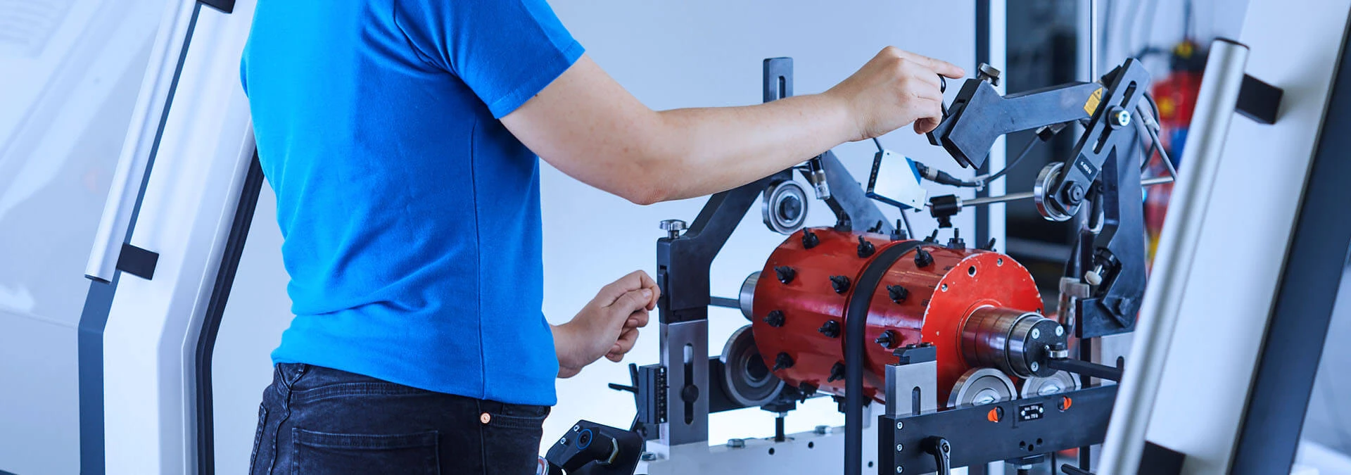
Below, we explain step by step how a balancing machine works, what types of balancing machines are available, and how to choose the right solution for your application. Our expertise ranges from rotors weighing just a few grams in small-scale applications to turbines weighing several tons, including those used in power generation. For more than a century, we have helped companies around the world select the right balancing solution for their specific requirements.
What Is a Balancing Machine?
A balancing machine measures the unbalance of a rotating component (rotor). Unbalance generates unwanted centrifugal forces that can cause vibrations and increased bearing wear. A balancing machine precisely detects the unbalance and enables targeted correction, helping ensure smooth, efficient operation and high reliability.
How Does a Balancing Machine Work?
A balancing machine supports the rotor, measures its unbalance, and calculates the correction required to compensate for it. Depending on the machine type and application, measurement and evaluation are performed in different ways, for example based on the measuring principle, the number of correction planes, and the rotor support system. The objective is always the same: precise correction of the unbalance.
Measuring unbalance: How does a balancing machine determine the location and amount of unbalance?
The rotor is set in rotation. Sensors detect the vibrations caused by unbalance as well as the resulting centrifugal forces or vibration displacement. Based on these measurements, the measuring system calculates how much mass must be added or removed at a specific angular position in each correction plane.
On manually operated balancing machines, each correction is followed by a verification run until the required balancing quality is achieved. The measuring system is at the heart of this process. At Schenck, this includes the measuring systems of the CAB family and the Schenck ONE software platform. They digitally process the measured values, provide a visual representation of the unbalance, and guide the operator through the individual process steps required to correct the unbalance.
Static or dynamic balancing: Balancing in one or two planes?
Whether one or two correction planes are required depends on the type of unbalance.
- Static unbalance: Static unbalance occurs when two unbalances have the same direction and angular position. The principal axis of inertia is parallel to and offset from the axis of rotation. Even when stationary, the rotor tends to settle with its heaviest point at the bottom. Correction is performed in one plane. In practice, this is often the case with flat or disk-shaped rotors.
- Dynamic unbalance: This type of unbalance is particularly common with longer, cylindrical rotors. The principal axis of inertia is inclined and offset relative to the axis of rotation. When the rotor rotates, this results in a wobbling motion. Correction is performed in at least two planes.
Force-measuring or displacement-measuring: What is the difference between hard-bearing and soft-bearing balancing machines?
Balancing machines measure unbalance using two physical principles that differ primarily in how the rotor is supported.
| Characteristic | Force-measuring (hard-bearing) | Displacement-measuring (soft-bearing) |
| Bearing supports | Very rigid | Flexible |
| Measured variable | Centrifugal force | Vibration amplitude (displacement) |
| Measuring speed | Below the natural frequency | Above the natural frequency of the suspension system |
| Calibration | Permanently calibrated | Calibrated for the specific rotor |
Unbalance correction: How is unbalance corrected?
Unbalance is corrected by adding or removing mass at the calculated position. Possible correction methods include:
- Drilling,
- Milling,
- Grinding,
- Welding,
- Adding screws or threaded weights,
- Bonding.
The appropriate correction method depends on the rotor. Axle drives, for example, can be corrected by drilling and, optionally, by welding at the drive flanges. For crankshafts, the measuring system calculates the correction in a way that minimizes the number of holes required. In many cases, a single correction step is sufficient. On manual balancing machines, the operator performs the correction, while in automatic balancing systems, the correction process is integrated directly into the machine cycle.
What Balancing Quality Does Your Rotor Require?
The required balancing quality depends on the rotor type, rotor mass, and maximum operating speed.
For rotors with rigid behavior, DIN ISO 21940-11 defines the procedures and permissible unbalance tolerances.
The standard uses balance quality grades G, expressed in mm/s. The lower the G value, the lower the permissible residual unbalance and the tighter the tolerance. The permissible residual unbalance for your rotor is determined based on the balance quality grade, rotor mass, and rotational speed.
For guidance, the standard provides reference values:
- G 2.5: for example, gas and steam turbines, machine tool drives, and medium-sized and large electric motors
- G 6.3: for example, fans, pumps, pulleys, and flywheels
Important: In practice, zero residual unbalance cannot be achieved. The tolerance should therefore be defined at an economically reasonable level, balancing the requirements for quality and cost.
For flexible rotors, such as large turbines and generators, this approach alone is not sufficient. Unlike rigid rotors, flexible rotors can change shape due to deflection across the operating speed range, which can also cause the measured unbalance values to change.
What Types of Balancing Machines Are There?
Different types of balancing machines are used depending on the rotor geometry, rotor size, and application. In general, a distinction is made between horizontal balancing machines, vertical balancing machines, static balancing machines, high-speed balancing machines, and portable balancing systems. Depending on the production requirements, balancing machines can also be designed for manual, semi-automatic, or fully automatic operation.
Horizontal Balancing Machines for Cylindrical Rotors
Horizontal balancing machines are suitable for cylindrical rotors with their own shaft journals and for disk-shaped rotors mounted on an auxiliary shaft. The rotors are supported on adjustable roller bearings or, where required, plain bearings. Depending on the application, they are driven by either a belt drive or a cardan shaft drive.
At Schenck, three product families cover rotor weights ranging from 5 g to 250,000 kg:
- Pasio: for small to medium-sized rotors weighing up to 700 kg, featuring Schenck ONE software, a small footprint, and tool-free changeover
- HM: for large rotors weighing up to 250,000 kg, with a modular design ranging from HM 4 to HM 80
- HL: for turbines and compressors weighing from 200 g to 5,000 kg in the aerospace industry
Typical rotors include electric motor armatures, rolls, spindle shafts, pump rotors, fans, generators, and turbines.
Vertical Balancing Machines for Disk-Shaped Rotors
Vertical balancing machines are designed for balancing disk-shaped and cup-shaped rotors without their own bearing journals. Typical examples include brake disks, fan and pump impellers, clutch and transmission components, pulleys, and flywheels.
The Virio series of universal balancing machines mounts the rotor on a precision spindle, eliminating the need for auxiliary shafts. The machines are permanently calibrated and can be equipped with systems for unbalance correction. For series production, Schenck also offers automatic vertical balancing machines for disk-shaped rotors weighing up to 300 kg.
Static Balancing Machines: How Does Measurement Without Rotation Work?
Static balancing machines measure the mass distribution of disk-shaped rotors while they are stationary. Since the rotor does not rotate, there is no need for acceleration or braking time, and no safety enclosure is required. A high-precision centering device is sufficient.
The Taro and ESx models use three high-precision load cells. This enables true permanent calibration without readjustment and provides very high accuracy across the entire weight range, within approximately 1%. Taro is designed for rotors weighing from 200 to 3,600 kg and automatically determines the workpiece weight in addition to the unbalance. Typical applications include grinding wheels, brake disks, propellers, railway wheels, and pump impellers, in both manual and automated processes.
High-Speed Balancing Systems for Flexible Rotors
Flexible rotors deform at high rotational speeds and therefore need to be balanced close to their operating speed. High-speed balancing and overspeed testing systems are designed for this purpose.
For more than 70 years, Schenck RoTec has been a leading global supplier of these specialized systems. The DH systems are used for power plant turbines and generators, high-speed compressors, industrial steam and gas turbines, as well as aircraft engine components. They enable high-speed balancing at operating speed, low-speed pre-balancing, and overspeed testing for strength verification.
Portable Balancing Systems for Field Balancing
Portable balancing systems balance rotors directly in their installed condition, eliminating the need to disassemble the machine or system. This process is known as field balancing or in-situ balancing.
The SmartBalancer 4 can be used for rotors of all weight classes at speeds ranging from 120 to 80,000 rpm and supports balancing in two planes. It operates with up to six sensors simultaneously. For vibration and condition analysis, the Smart VibroAnalyzer 90 and Smart VibroAnalyzer 95 complement the product portfolio. Don't want to invest in your own equipment? Our balancing specialists can perform field balancing at your site.
Manual, Semi-Automatic, or Fully Automatic: Which Level of Automation Is Right for Your Application?
The right level of automation primarily depends on production volume, cycle time, and product variety. Operator involvement and the required integration into existing production lines also play an important role. With manual balancing machines, the operator handles rotor changeover, the measuring run, and unbalance correction. Semi-automatic balancing machines perform individual process steps automatically, while fully automatic balancing machines handle the entire process chain, from loading the rotor to unbalance correction.
Universal Balancing Machines for Small Production Runs and Changing Rotor Types
Manually operated universal balancing machines are the right choice for individual parts, prototypes, small production runs, or applications involving different rotor types.
These balancing machines are not designed for one specific component. Instead, they can be configured for different rotors within their specified size range. Their modular design makes this flexibility possible: fixtures, bearing supports, drive systems, safety enclosures, and software can be configured to suit your specific balancing application. Precision adjustment mechanisms and scales allow you to change over quickly to the next rotor type. Here you can find an overview of all manually operated balancing machines.
Semi-Automatic and Fully Automatic Balancing Machines for High-Volume Production
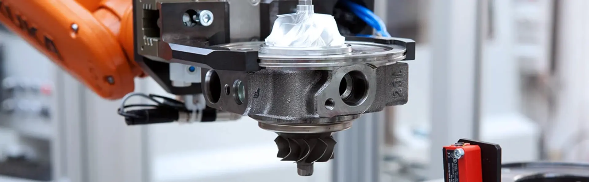
Automatic balancing machines are designed for high-volume production with demanding requirements for balancing quality, repeatability, and cycle time. They measure and correct unbalance without manual intervention, ensure consistently high quality, and provide complete documentation of tight tolerances.
Four characteristics are key: achievable cycle time, attainable tolerances, modular design, and reliable changeover between different rotor types. Communication interfaces enable the balancing machines to exchange data with production line control systems and Manufacturing Execution Systems (MES). Semi-automatic balancing machines offer a flexible and cost-effective solution for lower production volumes, while fully automatic balancing systems are designed for high throughput. Learn more about automatic balancing machines.
Complete Production Lines: Balancing as Part of the Manufacturing Process
In some industries, balancing is an integral process step within a complete production line. A prime example is complete wheel assembly.
Schenck's wheel assembly lines combine the assembly, inflation, balancing, and testing of wheels and tires. The portfolio ranges from stand-alone machines to fully automated, robot-assisted production lines and can accommodate a wide variety of products. Schenck plans and implements these lines as complete solutions, supported by a range of active patents in the field of wheels and tires.
Which Balancing Solution Is Right for Which Rotor?
The starting point is typically the specific balancing task. Rotor geometry, weight, speed, production volume, and manufacturing environment determine which balancing solution is most suitable. The following overview matches typical rotor types with the appropriate balancing solution.
| Rotor | Suitable Solution | Level of Automation |
| Rolls, shafts, spindles, pump rotors | Pasio, HM | Manual |
| Impellers, clutches, pulleys | Virio, Disk-Shaped Rotors | Manual to fully automatic |
| Grinding wheels, brake disks, railway wheels | Taro & ESx | Manual or automated |
| Crankshafts | Crankshafts | Manual to fully automatic |
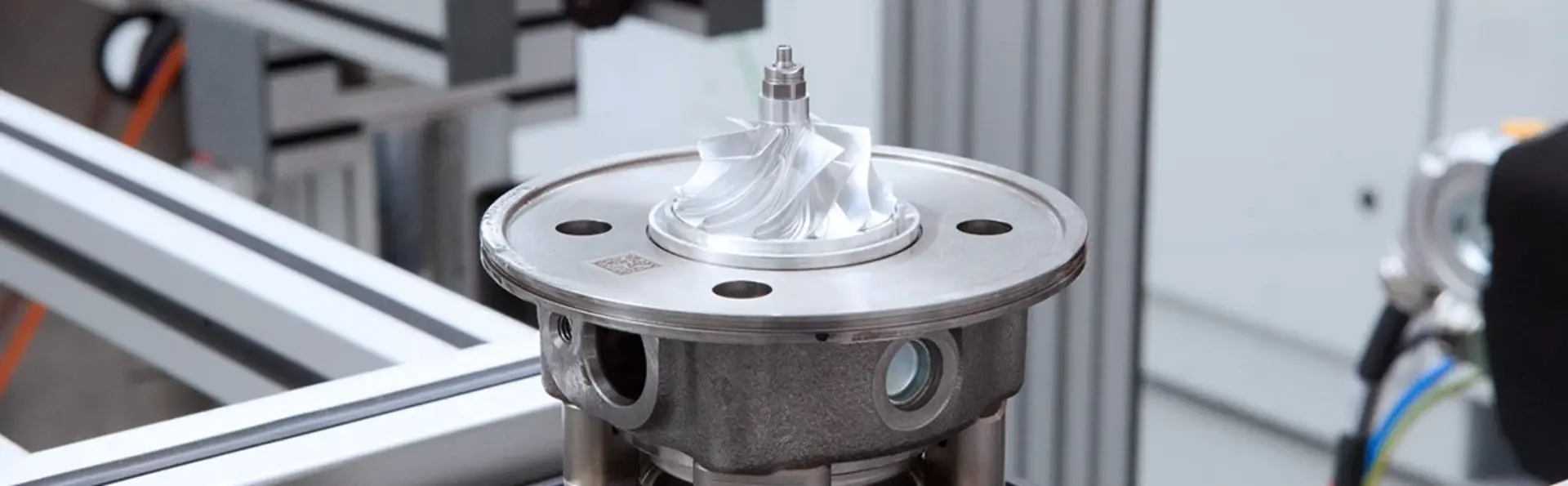
| Turbochargers, fuel cell compressors | Turbochargers & Components | Manual to fully automatic |
| Electric motor armatures | Electric Motor Armatures | Manual to fully automatic |
| Electric drive rotors | Electric Drives (eDrives) | Development to series production |
| Axle drives | Axle Drives | Semi-automatic to fully automatic |
| Torque converters | Torque Converters | Semi-automatic to fully automatic |
| Cardan shafts | Cardan Shafts | Automatic |
| Fans and blowers | Fans & Blowers | Automatic |
| Complete wheels | Wheel Assembly Lines | Semi-automatic to fully automatic |
| Aircraft engine components, satellites | Aerospace | Manual |
| Turbines, generators, compressors | DH Systems | System |
| Installed rotors | Portable Balancing Equipment | Portable |
Aerospace applications are subject to specific requirements. Schenck horizontal balancing machines for these applications comply with SAE ARP 4048. Moment weighing systems complement the portfolio and help optimize blade distribution on the rotor.
How Do You Choose the Right Balancing Machine?
The right balancing machine depends on the characteristics of your rotor and your production requirements. Use this checklist to identify the key criteria and prepare for selecting the right solution:
- Rotor geometry: cylindrical with shaft journals or disk-shaped without a shaft?
- Rotor weight and diameter: minimum and maximum values across your range of parts
- Rotor behavior: rigid or flexible?
- Balancing quality: required balance quality grade or permissible residual unbalance
- Correction planes: one, two, or more?
- Production volume and cycle time: one-off production, small batches, or high-volume production?
- Product variety: How often do you change rotor types?
- Correction method: drilling, milling, welding, balance weights, or other methods?
- Integration: stand-alone machine, production line integration, or MES connectivity?
- Safety: What type of safety enclosure is required, and could parts become detached from the rotor during the balancing run?
- Service: On-Site Maintenance, Inspection, and Training
Looking for the right balancing machine for your application? Our experts will help you find a solution that meets your rotor and production requirements. Alternatively, use our Product Finder to filter balancing solutions by industry and rotor type.
How Does Schenck RoTec Support You Throughout the Machine Lifecycle?
From the initial idea to the end of your machine’s service life, Schenck is there to support you. Every machine comes with a commitment to service, including consulting, software, and maintenance.

- Technical Consulting: Support from product planning through rotor design
- Contract and Field Balancing: We balance your rotors worldwide when you do not have the right balancing machine available
- Centrifugal Testing: Prototype testing and overspeed testing services at the Schenck Green Technology Center, using spin test systems such as Centrio for rotors weighing up to 6,300 kg
- On-Site Service: Maintenance and inspections according to the PFA method and ISO standards, health checks, and machine relocation
- Customer Service: Help desk, spare parts and loaner equipment services, repair center, Service+ App, and Interactive Support+
- Balancing Technology Test Laboratory (PFA): Accredited test laboratory for traceable validation of machines and reference standards
- Schenck Academy: Training in Darmstadt, at your site, or live online, tailored to rotor types and roles such as operators, maintenance personnel, and design engineers
- Modernization: The Schenck ONE modernization package upgrades many existing universal balancing machines to current technology
Everything from a Single Source Throughout the Entire Lifecycle
From system planning and automation to digitalization, service, and modernization, Schenck RoTec supports you throughout the entire lifecycle of your products and machines. Explore our complete portfolio and discover all our solutions at a glance.
Why Choose Schenck RoTec Balancing Machines?
Schenck RoTec is the global market leader in balancing solutions, with extensive expertise in automation and digitalization. Our solutions enable safe, highly accurate, and resource-efficient manufacturing of products used by billions of people every day.
- Close to You Worldwide: 17 subsidiaries and joint ventures, six production sites, and more than 36 representatives and offices across five continents. Schenck RoTec locations and services are available in 54 countries.
- Quality and Precision “Made in Germany”: From engineering to manufacturing, our balancing machines are designed to meet the highest standards of quality and precision.
- Serving a Wide Range of Industries: Automotive and Suppliers, Electrical Engineering, Aerospace, Turbomachinery, and General Mechanical Engineering
- Technology: permanently calibrated balancing machines, modular systems, and digitalized measurement and correction processes
- Experience: More than a century of experience and expertise gained through numerous projects.
- Partnership: We are your consulting and technology partner for balancing solutions throughout the entire product lifecycle, not just a machine manufacturer.
Frequently Asked Questions About Balancing Machines
-
Are “Balancing Machine” and “Balancing System” the Same Thing?
-
Not exactly. A balancing machine is the machine used to measure and correct rotor unbalance. The term “balancing system” is broader and is often used for solutions that combine measurement technology, software, and automation.
-
Why Can’t Unbalance Be Completely Eliminated?
-
There is no such thing as absolute zero unbalance in practice. Some residual unbalance always remains after balancing. What matters is that the residual unbalance stays within the specified tolerance. In most cases, reducing unbalance beyond the required level is not economically practical.
-
How Large and Heavy Can a Rotor Be?
-
The appropriate balancing machine depends on the specific design. Schenck horizontal balancing machines cover rotors weighing from 5 g to 250,000 kg. The Pasio series handles rotors weighing up to 700 kg, while the HM series accommodates rotors weighing up to 250,000 kg. The Taro static balancing machine is designed for rotor weights from 200 to 3,600 kg. Detailed limits for rotor weight, diameter, and shaft journal dimensions can be found in the data sheets for each product family. For special applications, custom balancing machines can also be used to balance rotors weighing more than 350,000 kg.
-
Does a Balancing Machine Need to Be Calibrated Regularly?
-
Force-measuring balancing machines are permanently calibrated and do not require a calibration run before measuring a new rotor. This applies, for example, to HM, Virio, Taro, and ESx machines. Regular inspections are recommended to ensure that your measurement results remain reliable and traceable over time. Schenck On-Site Service performs these inspections in accordance with the PFA method and ISO standards.
-
Can a Rotor Be Balanced While Installed?
-
Yes, through field balancing. The rotor is balanced directly in its installed machine or system without having to be removed. Portable balancing equipment such as the SmartBalancer 4 can be used for this purpose. Alternatively, Schenck’s field balancing service can perform the balancing directly at your site.
-
What Is the Difference Between a Wheel Balancer and an Industrial Balancing Machine?
-
Workshop wheel balancers are designed specifically for balancing individual complete wheel and tire assemblies. Industrial balancing machines, on the other hand, are used in manufacturing to balance rotors of many different types and sizes, from one-off production to high-volume production. For wheel and tire manufacturers, Schenck offers solutions ranging from individual machines to fully automatic wheel assembly lines.
-
What Cycle Times Can Automatic Balancing Machines Achieve?
-
Cycle time depends on the rotor type, its initial unbalance, the required balancing quality, the correction method, and the machine configuration. Therefore, a reliable cycle time can only be determined for the specific application. Our experts assess which measures can be used to achieve the required cycle time.
-
Can Schenck RoTec Customize a Balancing Machine for My Rotor?
-
Yes. Thanks to a modular design, workpiece fixtures, rotor supports, drive systems, safety enclosures, and software can be tailored to your specific rotor. For special requirements, Schenck develops customized solutions through its Technical Consulting services, ranging from individual balancing machines to complete production lines.